Book Cover
Spine
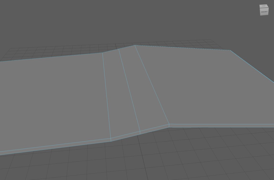
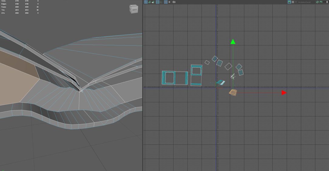
The beginning stage of the modelling process was a little difficult for me. I first began by creating a cube and scaling the proportions so it would resemble the shape of a book. Next, by selecting the multi-cut tool and holding CTRL, I was able to create edge loops around the areas I wanted to form the spine. Once creating the outline, in face mode, I used the move tool to move the spine upwards then used the bevel tool to create the curve shown in the screenshot. As books don’t have sharp edges, I selected the outer faces on either side of the book and beveled them to create the curve and by adding more segments, I was able to curve it more.
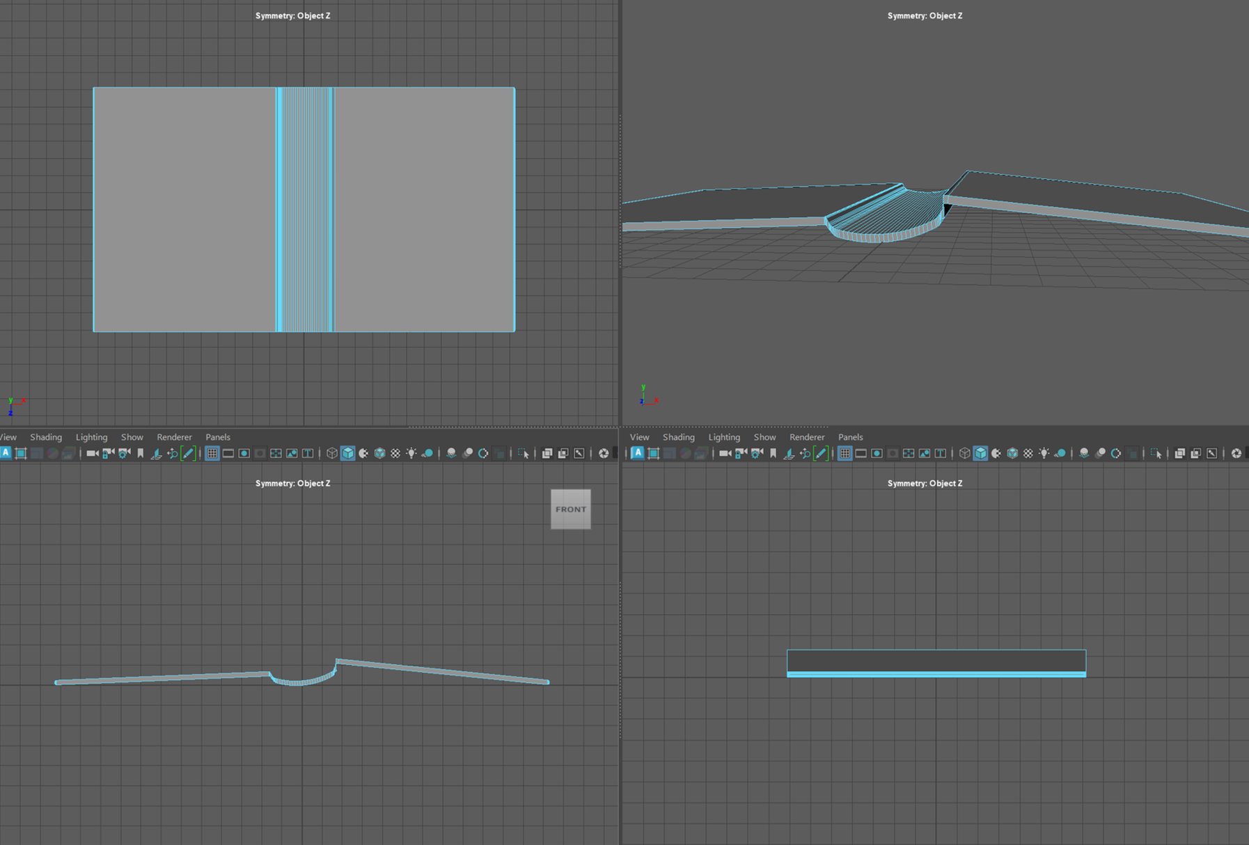
My initial concept was to create an open-paged book, and in order to maintain realism I wanted to create a “weighted” appearance (meaning one side has more pages); this is what led me to my first problem. When attempting to readjust one side of the book, I was unable to properly create a curve in the spine for it to reach the other side – resulting in a very flat face from the face of the right cover to the spine. To solve this problem, I started from the beginning but with a different method.
To begin with, I created a cube and reshaped it using the scale tool again. I used the bridge tool to connect the two faces together to form a new face for the spine.

Metal Bumps
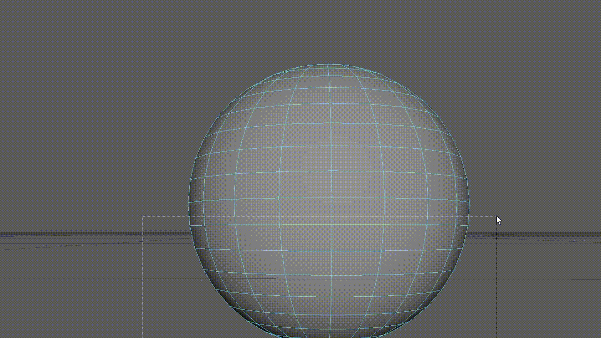
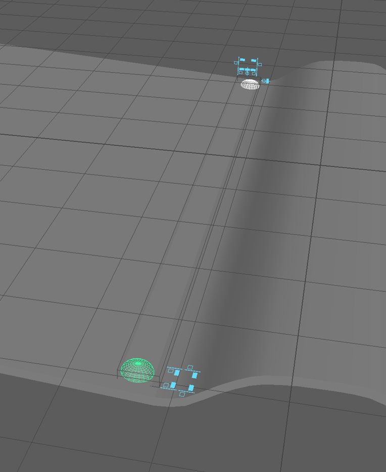
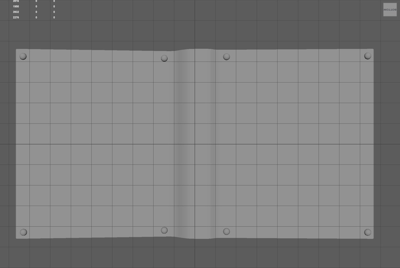
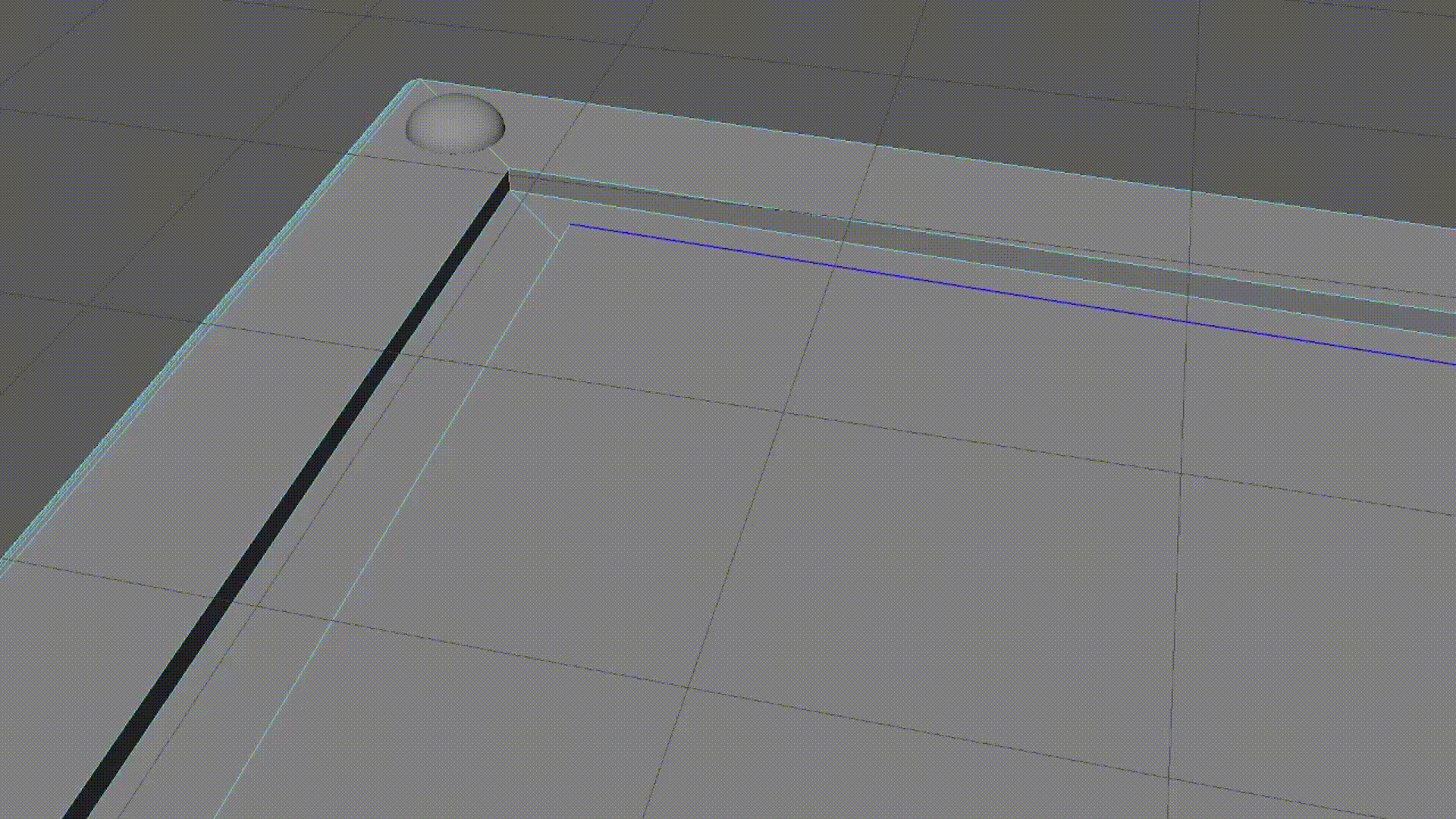
Following the concept art I designed, my next step was to create the small metal bumps that are laid out on the four corners of each side of the book cover. To create the bumps, I added a sphere into the scene and scaled to my desired size. Once scaled, I selected half the faces of the sphere and deleted them; this led to a hole beneath the now hemisphere, so I filled it in and beveled the edges.
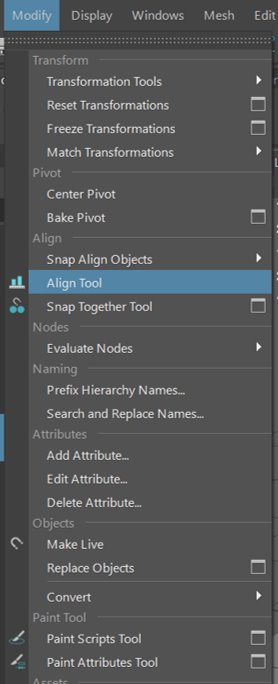
When positioning the hemispheres, I used the ‘Align Tool’ under the ‘Modify’ tab to align them so they were situated evenly opposite each other on the four corners. This process was repeated for the right side of the book cover.
Pages
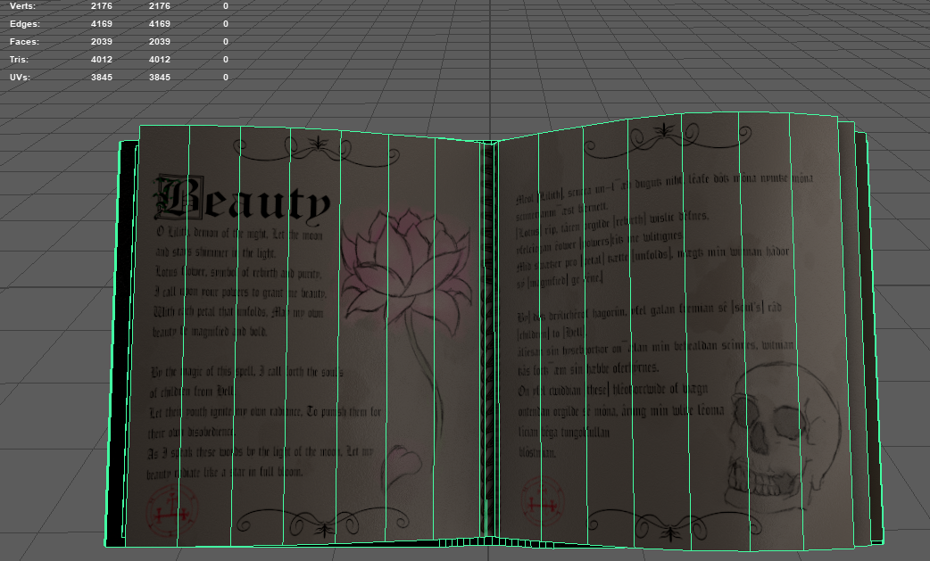
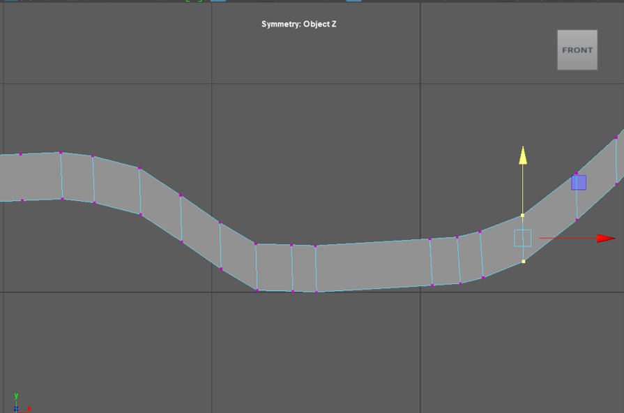
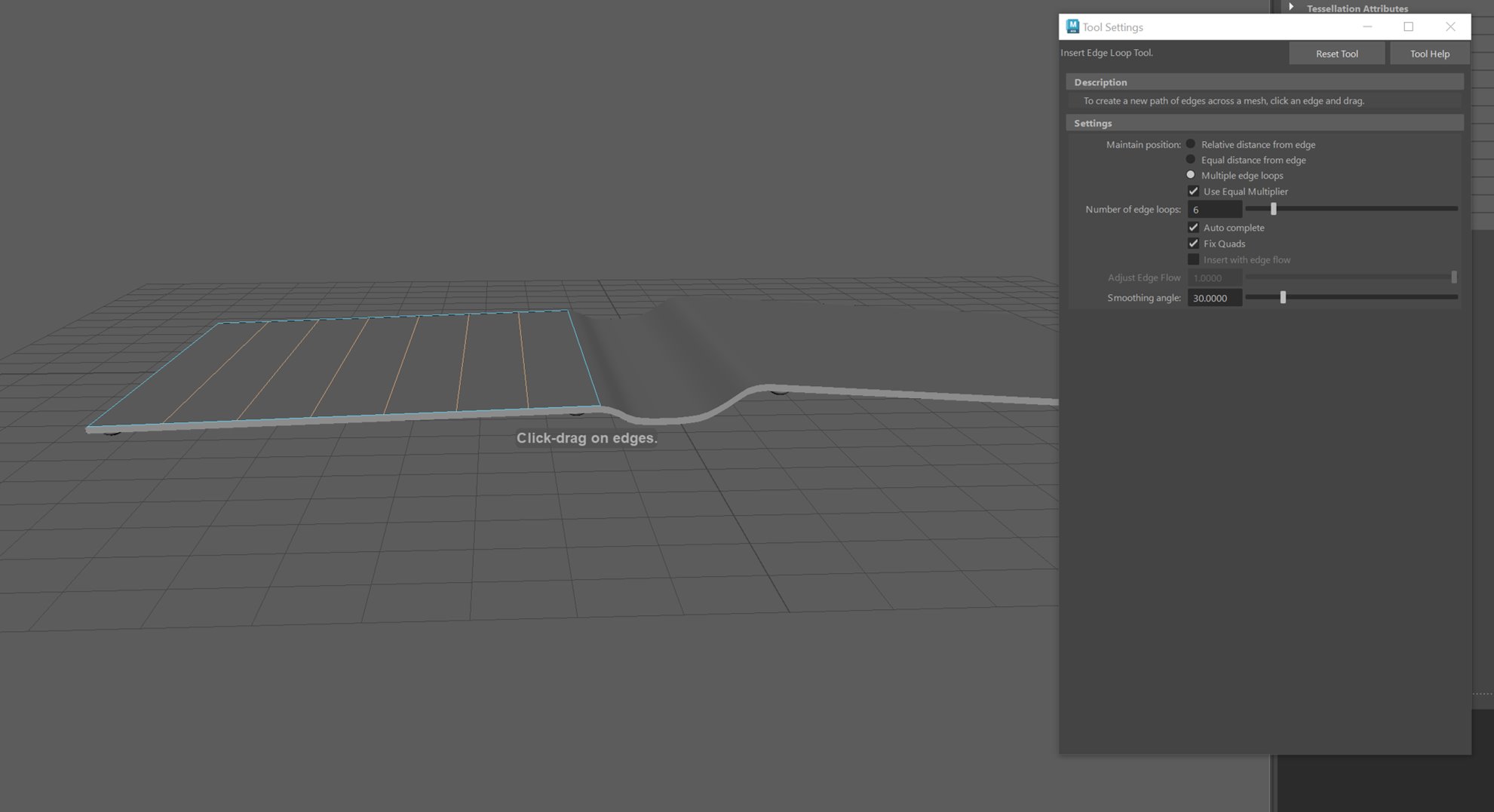
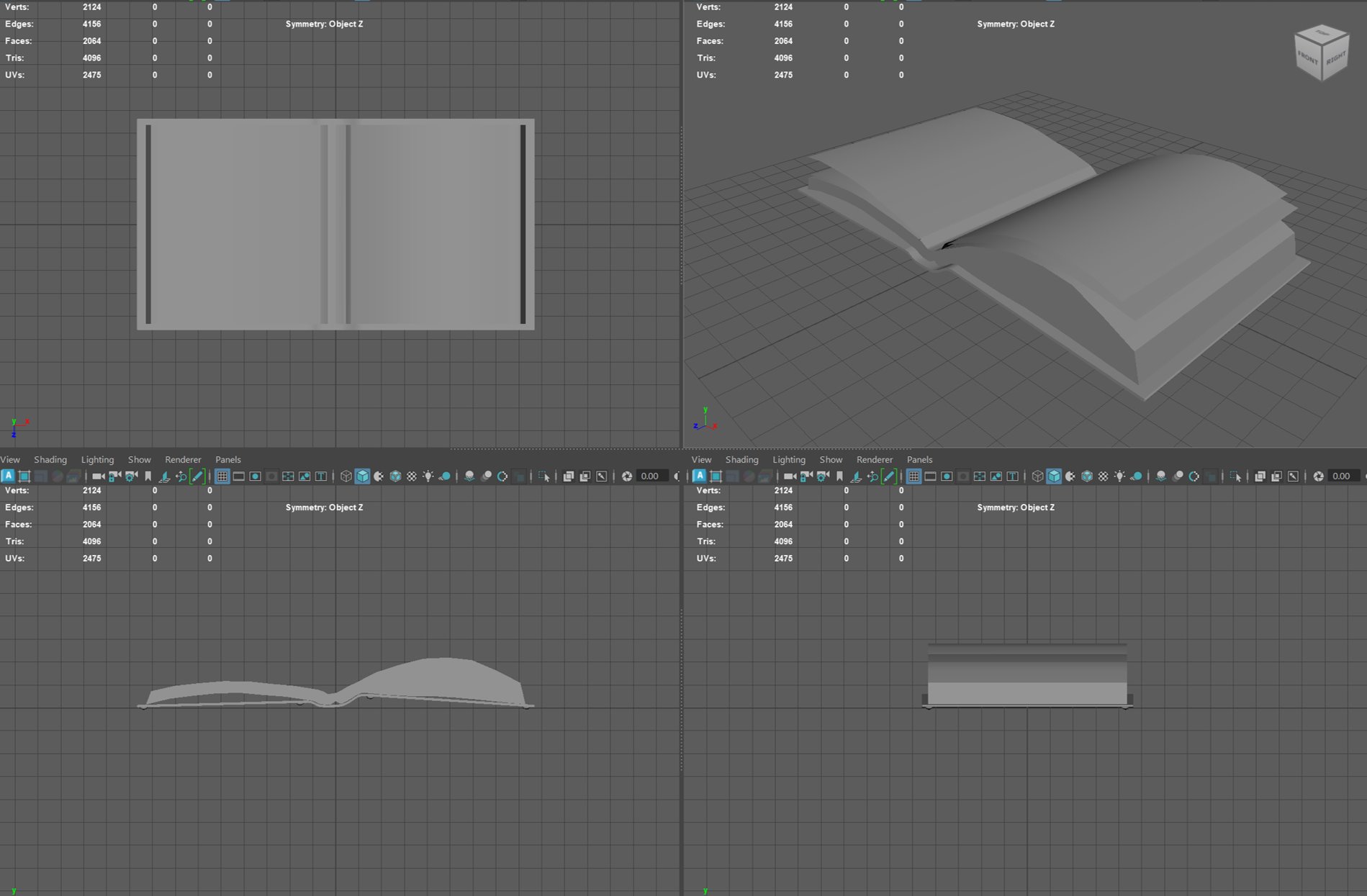
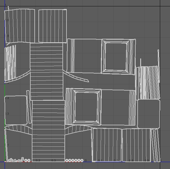
In order to create the pages, I needed to select the face and half of the spine (to resemble the paper lifting from the centre of the spine)and duplicate faces. The next step was to create edge loops but have them spread out evenly across the face. I then entered edge mode and selected the newly created edges and moved them upwards to mimic the appearance of the pages being stacked. Once this was done, I selected all the duplicated faces and extruded them upwards to generate a “thickness” to the amount of pages and moved towards the opposite direction of the spine so that the side would appear slightly slanted.
Once this was done, I needed to duplicate the faces again, but this time move the edges upwards so that they resemble the page being lifted. The same method was done on the opposite side, but with a thicker page to stay consistent with the weighted side I designed earlier on.
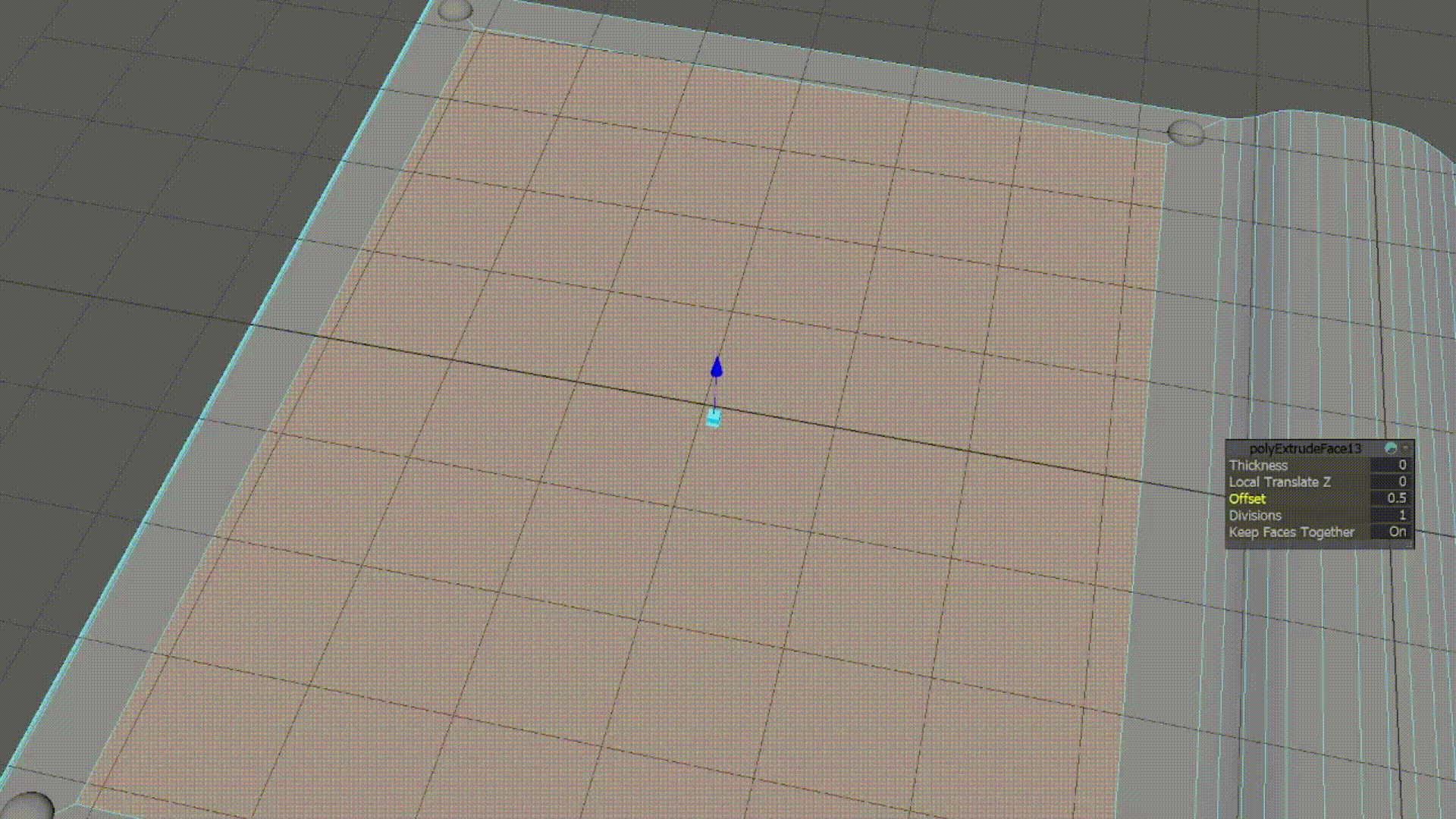
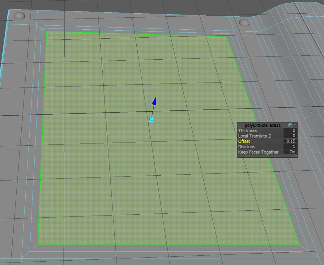
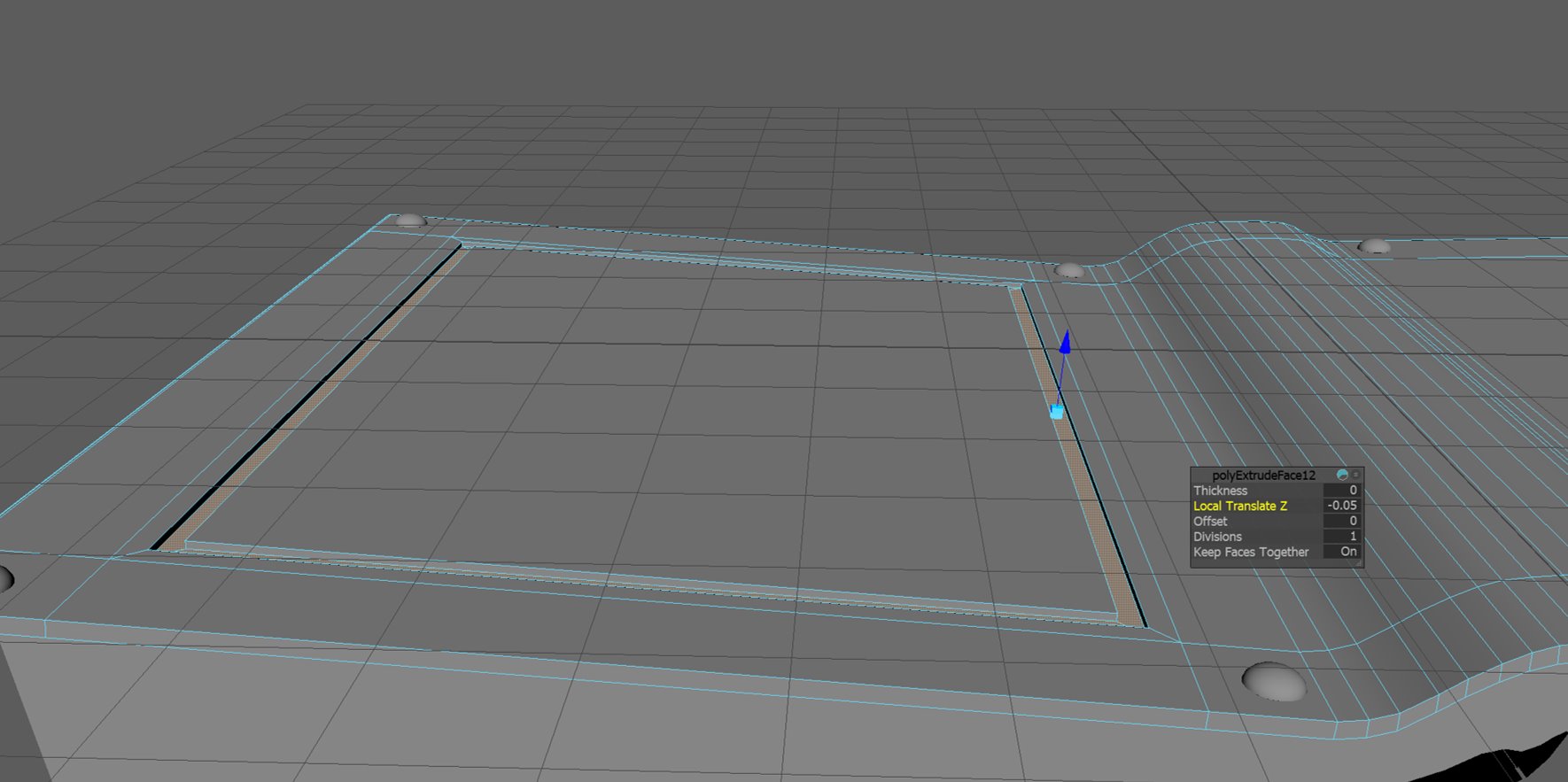
Indents
When creating the indents of the back of the grimoire, I created edge loops around the face of the left back cover which results in creating a new face at the centre. I selected the newly created face and selected the extrude tool but only altered the offset by 0.15. I repeated the process and extruded the faces of the middle area by -0.05.
Seal
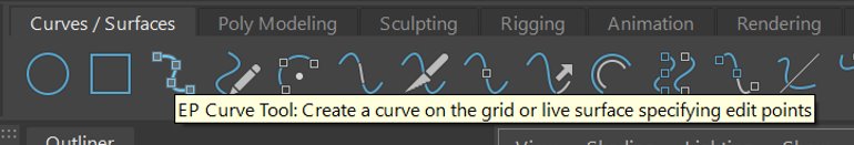
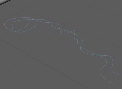
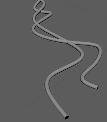
Using the EP curve tool, I attempted to create string. I first sculpted the curves that I wanted the string to appear like then created a sweep mesh. When adding a sweep mesh, it creates a large mesh and because my string is intended to be small, I scaled it to a smaller size. Using the precision scale under “Interpolation” I was able to create a smooth surface to resemble string. By ticking the distribute option, it splits the mesh into four (I altered by 5) then proceeded to adjust the twist to a higher value to create the thread appearance for the string.
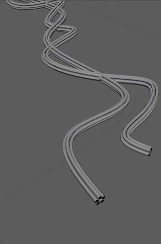
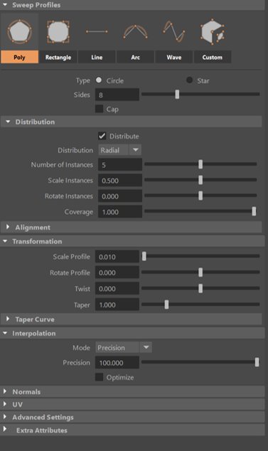
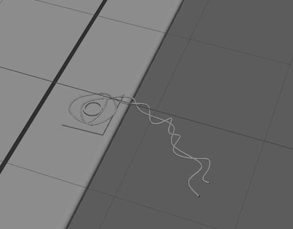

After creating the string and even lowering the value of the twist transformation, I realised that the poly count was still well over the appropriate amount; therefore, I decided to remove the seal completely.
UV
When beginning the process to unwrap the UVs, I deleted the current UVs for a clean state. From here, I positioned the camera then selected the camera-based UV; this allows me to create a new UV map from the perspective of where the camera is facing. Within the UV editor, I experimented with the cut and sew tool and optimised the unfolded UVs to create the desired unwrapping.
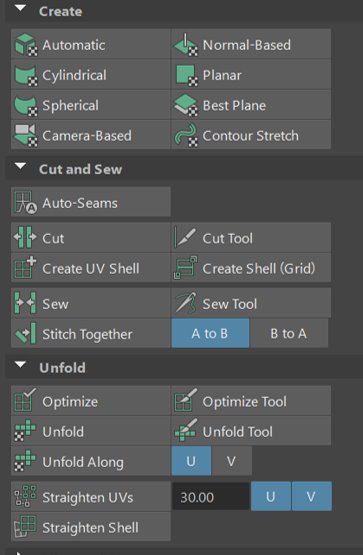
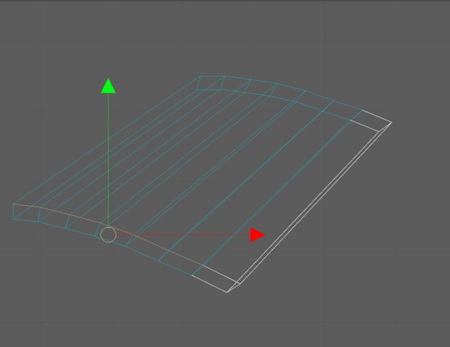
Once the UVs were unwrapped, I used the layout tool to automatically layout the UVs.